
Our product support both hot water and electric under floor heating system. While the electric system is a lot simpler and has fewer system variations, many would consider lesser efficient than the hot water system. Below is a simplified guide to the hot water systems. For professional advise, please consult an under floor heating system engineer. The information below is not a substitute for getting professional advice on your specific installation.
Water UFH System Type
Solid Floor System – Clips and Rails
Underfloor heating pipe is fixed to pre-laid insulation (for example, Celetex) using either 60mm clips, adhesive-backed clip and rail or a combination of both. Once laid and pressure tested the pipes are covered in typically 60-65mm of screed. This is generally considered as the most efficient form of underfloor heating with the conduction and heat storage abilities of the screed layer.
Solid Floor System – Fixing
An alternative to a Clips and Rail system is to use a Castellated Panel or Fixing panel system to secure the pipes. Once laid and pressure tested the pipes are covered in typically 60-65mm of screed. This is generally considered as the most efficient form of underfloor heating with the conduction and heat storage abilities of the screed layer. Castellated panels can also be provided with a thin layer of insulation on the under side where additional floor insulation is required.
Plate System
Aluminium diffuser plates are used to hold the pipes and conduct heat to create a more even temperature in timber joisted floors. Where the original joists are set at mostly 400mm centres then it is possible to lay the plates directly between the existing joists for minimum rise in floor levels. Any notching to existing joists must comply to building regulations. It is advisable that the plates are in direct contact with the floor decking and insulation is required below to avoid downward heat transfer.
Pug System
An alternative to the plate system is to use a ‘Pug’ system. This is useful when joist spacing is irregular or not at the right centres and a rise in the finish floor level is not possible. This can require more work to install, but does provide one of the best results on a suspended floor as it acts in the same way as a screed, where the sand/cement mix act an efficient conductor and a thermal store. Support is required below the insulation and a sand/cement mix is laid over the pipes and between the joists.
Overlay light System
1250x600x20mm foiled xps insulation panels, routed for 16mm pipe set at 150mm centres with three cross runs. These high-quality panels are best suited for floating floor applications and are not suitable for direct tiling over. Best practice is to apply a levelling compound to the floor substrate prior to laying the panels, and then to fit either a structural floor decking or a suitable engineered wood/laminate. Transit panels set at 50mm centres are also available to ease installations. (Typically allow 1.5 panels per 1sqm.)
Overlay Solid System
1200x600x20mm Cement faced xps insulated panels, routed for 16mm pipe set at 200mm centres. The panels require a solid base and should be stuck down with a flexible tile adhesive prior to laying and pipe. Once set, the panels are suitable to tile over, again using a flexible tile adhesive. Transit panels set at 50mm centres are also available to ease installations. (Typically use 1.5 panels per sqm)
Pipework Layout Type
Single Serpentine Flow
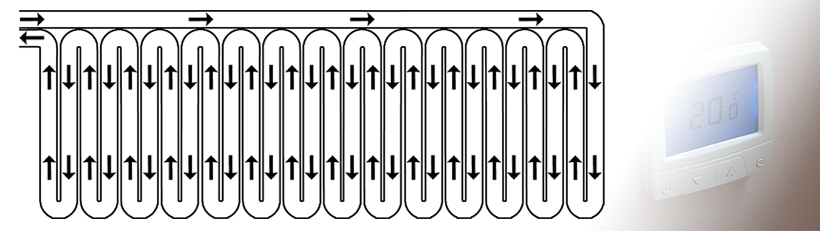
The simplest layout option is the single serpentine. In this design, a single pipe enters the room and uses a ‘zig-zag’ motion to span the length of the room. The pipe then exits through the entry point. Though this method provides an easier installation, it can distribute heat unevenly. The hot water which enters the room gradually cools as it runs through the system. At the entry point, the system has a higher heat output, thus the room becomes cooler at one end. This method is predominantly used when installing spreader plates.
Double Serpentine Flow
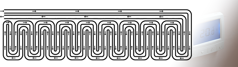
In a double serpentine layout, the pipe enters and runs along the perimeter of the room, before creating a ‘zig zag’ layout, then running back on itself to create a contraflow. The cooler water, therefore, runs alongside the warmer water nearer to the pipe entrance, allowing the temperature to even out throughout the room. This is an effective method to create a more even distribution of heat.
Concentric Flow
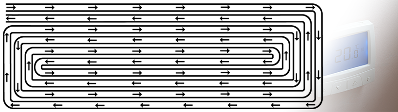
In this flow layout, the pipe is run around the perimeter of the space, then repeatedly tracked around the room, creating a spiral shape, before reaching the centre. The pipes deliver the most heat around the outskirts of the room, where heat naturally escapes, while the centre of the room is heated the least by the system. As heat loss is usually at its lowest in the centre of the room, the temperature across the room should average out.